
Edit Project Variant
Parent page: WorkspaceManager Dialogs
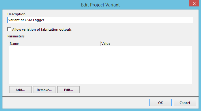
The Edit Project Variant dialog.
Summary
This dialog provides the designer with the controls required when initially adding a new variant for the design, or editing/cloning an existing one. It simply allows the variant to be given a meaningful name, as well as the ability to specify variant-level parametric data.
Access
The dialog is accessed from the Variant Management dialog in the following ways:
- When adding a new variant for the design, by clicking the Add Variant button.
- When editing an existing variant for the design. With the required variant made active, click the Edit Variant button.
- When cloning an existing variant. With the required variant to be cloned made active, click the drop-down arrow at the right side of the Add Variant button, then choose the Clone Selected Variant command from the menu.
Options/Controls
- Description - use this field to give the variant a meaningful name. A meaningful name can not only aid in distinguishing between multiple defined variants, but also can provide some indication as to the purpose of that variant.
- Allow variation of fabrication outputs - enable this option to allow the variant to drive fabrication outputs for your design. Essentially, this feature allows you to vary the comment for a component in your design, and feed this change through to the following fabricated outputs:
- Gerber files
- ODB++ files
- Composite Drill Drawings
- Drill Drawing/Guides
- Final Artwork Prints.
More specifically, this concerns the silkscreen layer – the layer upon which the component comment will appear.
- Parameters List - this region lists all of the parameters currently defined for the variant, in terms of:
- Name - the name of the parameter.
- Value - the value of the parameter.
- Add - click this button to add a new parameter to the list. The Parameter Properties dialog will appear. Use this to define the parameter, in terms of its Name and Value.
- Remove - click this button to delete the currently selected parameter(s) from the list.
- Edit - click this button to modify the currently selected parameter. The Parameter Properties dialog will appear, with which to do so.
Working with Variant Parameters
PCBWorks supports parameters at various levels of the project. For example, you can add document-level parameters to each schematic sheet in the Document Options dialog. You can also add project-level parameters to the project, on the Parameters tab of the Options for Project dialog. Parameters can also be added to a variant, here in the Edit Project Variant dialog.
Parameters have a hierarchy, which means you can create a parameter with the same name at different levels of the project, each having different values. PCBWorks resolves this in the following way:
- Variant (highest priority)
- Schematic document
- Project
That means the parameter value defined in the schematic document overrides the value defined in the Project options, and the value defined in the variant overrides the value defined in the schematic document. Note that schematic-level parameters are not available on the PCB or in the BoM, for these types of output you should use project or variant parameters.